 Machine Safety
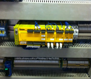
AC-Sys is fully aware of the importance of correctly implemented safety circuits, and over the last three years have desinged over 200 machine safety circuits for a major blue chip company for total compliance with EN ISO 13849-1.
A significant revision in EN ISO 13849-1 is the probabilistic approach to the assessment of safety-related control systems. This revision provides EN 954-1 with the probabilistic techniques urgently needed in order to assess modern circuits. This has been achieved by continuing to use the proven categories but to also assess quantitative safety-related features.
Performance levels (PL) have come into use; these are based on the categories and are described by the following parameters:
- Category (structural requirement),
- Mean time to dangerous failure ( MTTFd )
- Diagnostic coverage (DC) and
- Common cause failure (CCF).
As with all our systems we will interface with you and your colleagues to improve your understanding and ensure you are comfortable with the design philosophy and decisions made. Our values are clear in that the system should perform upon demand to meet the regulation while not being over engineered. We follow a clear design protocol which includes:
Step 1 - Define the safety function requirements
First of all it's necessary to establish the features required of each safety function. This step is the most important and sometimes the most complex. For safety gate guarding on a machine, for example, hazardous movements must be shut down when the safety gate is opened; it must not be possible for the machine to restart while the safety gate is open.
Step 2 - Determine the required performance level PL
The greater the risk, the higher the requirements and reliance on the control system.
The contribution of reliability and structure can vary depending on the technology used. The level of each hazardous situation is classified in five stages from "a" to "e". With PL "a" the control function's contribution to risk reduction is low, with PL "e" it's high. The risk graph can be used to determine the required performance level ( PLr ) for the safety function described above.
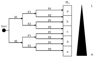 Severity of injury (S)
S1 = Slight (normally reversible) injury
S2 = Serious (normally irreversible) injury, including death
Frequency and/or exposure to a hazard (F)
F1 = Seldom to less often and/or the exposure time is short
F2 = Frequent to continuous and/or the exposure time is long
Possibility of avoiding the hazard (P)
P1 = Possible under specific conditions
P2 = Scarcely possible
Step 3 - Design and technical realisation of the safety functions
The "safety gate interlock" safety function described in Step 1 is realised through control measures. The safety gate interlock can implemented using a coded proximity switch. This provides the option to connect several safety gates in series without reducing the effectiveness of the monitoring functions.
The sensors are evaluated using a multifunctional safety system. The drive is shut down via two contactors with positive-guided contacts.
Step 4 - Determine and evaluate the performance level
The safety function is broken down into three parts to determine the performance level that has been achieved: input, logic and output. Each of these subsystems contributes to the safety function.
Step 5 - Verification
This step determines the extent to which the achieved performance level matches the required performance level. The achieved PL must be greater than or equal to the PL r required by the risk assessment. This means a "green light" for the machine design.
Step 6 - Validation
Alongside the purely qualitative requirements for the design of safety systems, it is also important to avoid systematic failures.


To discuss your requirements, call us today on +44 (0)7795 498018 or complete an enquiry form.